Uploaded
Submitted by: nickcinquino Project Website: cinquino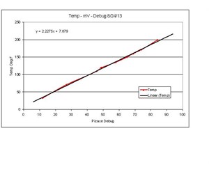
Uploaded
Submitted by: nickcinquino Project Website: cinquino
Easy Thermocouple to Picaxe Interface Nick Cinquino 8/28/2013
Thermocouples are a convenient sensor for the measurement of temperature
They have two important advantages over thermistors; a very linear response instead of a curve over a wide temperature range which allows for easy calibration/calculation of expected value, and very high maximum working temperature, often over 1000C, which would quickly "smoke" most thermistors.
Quick thermocouple overview: composed of 2 dissimilar metal alloy wires in contact with each other, either twisted or welded.
They display the Seebeck effect, in which a small voltage, typically just a few millivolts is generated.
A common variety is Type K, made from the alloys Nickel-Chromium and Nickel-Aluminum.
Type K thermocouple wire is very inexpensive.
I wanted to apply thermocouple sensing to the ADC input of Picaxe chips for several projects.
The obvious solution is to use the MAX6675 thermocouple to digital converter, but these are expensive and require additional serial-in programming of the Picaxe.
I wondered if there's an easier way… The ideal analog setup would be to apply considerable amplification, to bring the millivolt-level signal up into the volt range, and it should be single-supply, at 5VDC, to stay within the acceptable ADC input specification of the Picaxe chip.
The inexpensive LM324 quad opamp came to mind as a candidate.
Looking at online discussions, the odds of successful use of the LM324 opamp with thermistors seemed doubtful…commentators would point out the input offset voltage of the 324.
I wanted to see just how good/bad the functionality was, so I tested it out.
For general purposes, it works great! In the schematic, one of the 4 opamps of the LM324 is shown.
Since it's a quad opamp, you can have 4 thermocouples monitored by one Picaxe if desired…measure all kinds of heat flow! The theoretical gain is x390, with 3.
œ9Meg ohm feedback and 10k ohm resistors.
The output of the opamp can safely be applied directly to the ADC input of the Picaxe, in this case a 14M2.
Power is 5VDC, same as the Picaxe, never below 0 or above 5 to keep the Picaxe safe and happy.
The output tops out at 3.
œ9 – 4 VDC, so figure on that being the top end of the calibration (debug value of 0-200).
The schematic also shows a 3-color RGB LED.
In the application example shown, we are making a "Smart Coffee Stirrer", or a "Wildly Overcomplicated Drink Stirrer".
The possibilities are endless! It would not take much additional programming and circuitry for the Picaxe to control a relay, switching power to a heater, to hold the coffee or other application to a constant temperature.
You might think coffee temperature is a trivial issue, but research is done on this subject and papers published, such as Calculating the optimum temperature for serving hot beverages, Brown and Diller, University of Texas.
They found that, out of a group of 300 subjects, the ideal temperature range was 140 +/- 15 degrees F, with a calculated ideal of 136 F.
Do you know what temperature your coffee is right now? Brown and Diller also point out that drinks are often served far hotter, constituting a scald risk.
The Smart Coffee Stirrer monitors the temperature of your cup of coffee, and communicates with you, via LED color, the advisability of taking a gulp.
I place the sensing end of the TC inside a 3/16" glass tube, sealed at the tip.
A closed plastic tube should work as well.
The type K thermocouple will often have a yellow and red wire; red connects to ground and yellow to the opamp input per the schematic.
The "Smart Stirrer" also includes calibration functions (blinks blue in icewater, and blinks red in boiling water) and out-of-range indication (blinks white if temperature is above boiling or below freezing).
Steady green light indicates room temperature; alternating red/blue indicates ideal drinking range; steady red indicates scald risk; steady blue indicates cold.
The circuit can be assembled and used on a breadboard as shown in the photos.
Calibration: Calibrating the TC-Picaxe circuit is easy.
Download the program "Easy Thermocouple to Picaxe Interface" to the 14M2.
Open the debug window.
At minimum you need a cup of icewater, and a cup of boiling water.
With the circuit constructed as shown, and the TC in a glass or plastic sealed tube, dip it into the icewater.
Stir it around for a few minutes.
Note the debug value, and what the LED is doing.
Dip into boiling water.
Note debug and LED status.
If you have an additional thermometer, note temperature vs.
debug values as the water cools all the way down to room temperature.
You should end up with a calibration curve looking very similar to that shown in the pic/video.
For the circuit as shown, resolution is about 3F per debug reading.
Increase the opamp gain for higher resolution/lower max temp, or decrease gain for lower resolution/higher max temp.
Following is the program used for the "Smart Coffee Stirrer"…
;Thermocouple to LM324 to 14M2 NJC
main: readadc C.0, b1
debug b1
if b1 = 97 then outofrange
light1: high 3
low 1,2
pause 250
low 1,2,3
goto main
light2: low 2,3
high 3
pause 500
goto main
light3: high 2
low 1,3
pause 500
goto main
light4: high 2,3
low 1
pause 500
goto main
light5: high 1
pause 250
low 1
high 3
pause 250
low 3
goto main
light6: high 1
low 2,3
pause 250
goto main
light7:high 1
low 2,3
pause 250
low 1
pause 250
goto main
outofrange:
high 1,2,3
pause 500
low 1,2,3
pause 500
goto main
Additional TC considerations: schematics of very accurate thermocouple measuring instruments are often extremely complex, with "cold junction compensation".
This is due to the fact that every connection in the input circuit constitutes a thermocouple! To minimize this, keep the input as simple as possible.
I solder short leads (leftover wire from trimming resistors) to the input end of the thermocouple wire, and plug that directly into the breadboard.
Also try to keep all these assorted "accidental" thermocouples at constant temperature…only the sensing end of the thermocouple should be changing.
Then, we calibrate with the setup as is.
Thermocouple welding: Twisting together the bare ends of thermocouple wire works fine, but most professional TC's have been welded; there's a small bead at the tip where the wires were melted together.
Just for fun I wanted to weld the ends of my sensors also.
I used a 120VAC "stick welder", set to 100 amps output, and clamped a rectangular piece of graphite (an unused motor brush) in the ground clamp.
An alligator-clip jumper was connected to the stick holder, and the back end of the TC wire pair was connected to the alligator jumper.
With gloves, brush the tip of the TC twisted pair across the graphite momentarily.
After a few tries, a nice molten bead is the result! See video for additional detail on TC welding.
Keep in mind that welding is optional; twisting the ends together is sufficient, but welding the tip can be another fun aspect of Thermocouple/Picaxe interfacing.

Share