Please ensure you have read the following section before starting:
WJEC / EDUQAS A Level Assembler – Overview
One Time Initial Installation
- Install the latest version of PICAXE Editor 6 (WJEC compiler added in v6.0.9.0, Jan 2017).
- Install the AXE027 drivers (if AXE027 cable has not been used before). Instructions here.
- Click Start>All Programs>Revolution Education>PICAXE Editor 6>PICAXE Editor 6 to start the software.
- Select File>Options from within PE6
- From the Compiler tab disable (uncheck) the BASIC language pre-processor (at top of list).
- From the Compiler tab enable (check) the PICAXE-18M2 (WJEC Assembler) special type compiler (towards bottom of list).
- From the Colours/Fonts tab enable custom colour scheme, click Browse button, navigate to the Syntax folder and select the WJEC Assembler colour scheme file. This is not essential but does then enable correct colour coding of the assembler mnemonics as they are typed.
- Click OK to save and exit the Options dilaog.
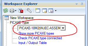
- From the Workspace Explorer>Settings tab select the PICAXE-18M2 (WJEC Assembler) compiler.
- From the Workspace Explorer>Settings tab select the correct COM port for the AXE027 PICAXE USB download cable.
The system is now ready for use (and will remember these settings when next started).
Instruction Set
The full Microchip MPASM instruction set is supported. However please refer to the EDUQAS/WJEC specification for the subset of instructions the students are expected to learn.
A student mnemonics reminder sheet can be downloaded here.
Pre-defined Special Function Registers
PORTA, PORTB = bi-directional input / output ports
TRISA, TRISB = data direction control registers for the ports
STATUS = STATUS register
INTCON = interrupt control register
TRISA and TRISB are on register page 1, so must be preceded by BSF STATUS, RP0
All other registers used for the WJEC course are on register page 0 (BCF STATUS,RP0).
Pre-defined general purpose registers
The following file registers are predefined and available for general use - B0 to B27. They are assumed to be on memory page 0.
Registers and constants can be renamed using EQU
 redLED  EQU   d'1'
 wSave   EQU   B20
Pre-defined constants
Instruction set
- W = result saved to the working register (h'00')
- F = result saved to the file register (h'01')
- C = STATUS carry bit (set if if an addition or subtraction result was > 255 or < 0, clear otherwise)
- Z = STATUS zero bit (set if the result of the last calculation was 0, clear otherwise)
- RP0 = STATUS register page selection bit
- GIE = INTCON global interrupt enable bit
- INT0IE = INTCON interrupt0 interrupt enable bit
- INT0IF = INTCON interrupt0 interrupt flag bit (set if the interrupt has occurred)
Radix
The default radix is set to decimal. However the preferred radix notation as used in these tutorials is:
 d’123’      decimal
 b’10101010’ binary
 h’FF’       hex
Assumed sub-routines for project work.
For PICAXE use the following sub-routines are assumed predefined to enable ‘real-life’ extension project work.
call wait1ms    ; delay 1 millisecond
call wait10ms   ; delay 10 milliseconds
call wait100ms  ; delay 100 milliseconds
call wait1000ms ; delay 1000 milliseconds
call readadc0   ; read analogue value on A.0 and copy into b0
call readadc1   ; read analogue value on A.1 and copy into b1
call readadc2   ; read analogue value on A.2 and copy into b2
call readtemp0  ; read DS18B20 temperature value on A.0 and copy into b0
call readtemp1  ; read DS18B20 temperature value on A.1 and copy into b1
call readtemp2  ; read DS18B20 temperature value on A.2 and copy into b2
call debug      ; upload variable values to computer screen
call lcd        ; send byte value in working register out of pin B.0 to LCD (2400,N,8,1)
Getting Started - Flash LED on and off
Type in the following example to flash an LED on pin B.1
 init:
     bsf    STATUS,RP0   ; memory page 1
     movlw  b'11111101'  ; set pin B.1 to output
     movwf  TRISB        ; write to TRIS register
     bcf    STATUS,RP0   ; memory page 0
 main:
     bsf    PORTB,1      ; output B.1 high
     call   wait1000ms   ; delay 1000 milliseconds
     bcf    PORTB,1      ; output B.1 low
     call   wait1000ms   ; delay 1000 milliseconds
     goto   main
Tip - to help check there are no typing mistakes click the ‘Syntax Check’ button.If you get a syntax error on line 3 make sure the PICAXE BASIC language pre-processor is switched off (installation step 5 above).
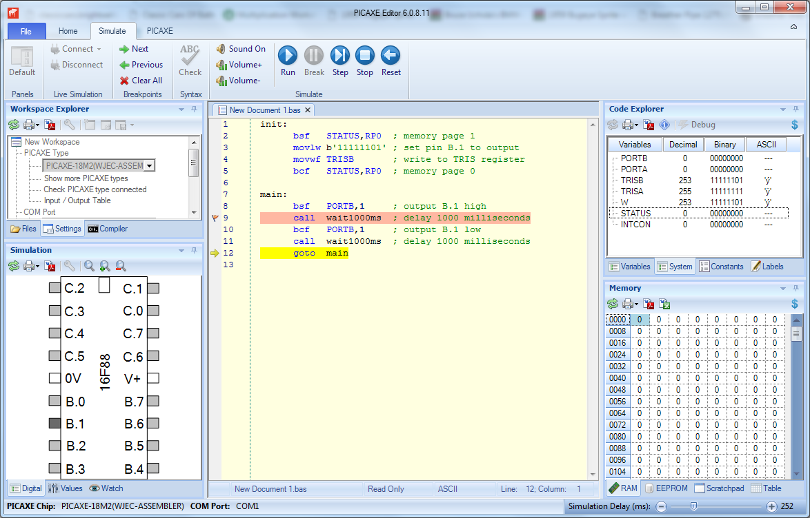
On Screen Simulation:
- From the Simulate ribbon click Run. Note that the speed of the on-screen simulation delay can be adjusted via the slider (bottom right).
- If you want to stop the simulation at a particular line click Break (or you can add a breakpoint flag by clicking in the left hand margin).
- To see the TRISB, STATUS etc. register values click on the System registers tab in the Code Explorer. For ease of viewing register bits make sure the ‘Binary’ column is displayed (right click over the display area if it is not).
- To alter a digital (switch) input left-click on the pin in the Simulation diagram.
- To alter an analogue (ADC) value right-click on the pin in the Simulation diagram.
Real life download to PICAXE-18M2 microcontroller:
For appropriate PICAXE hardware please see WJEC / EDUQAS A Level Assembler – Overview
- Make sure the project board is connected to the AXE027 download cable and powered.
- Make sure the correct COM Port is selected in the Workspace Explorer.
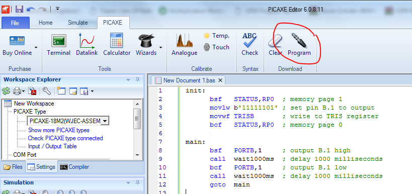
- From the PICAXE ribbon tab select Program.
After download the LED connected to pin B.1 should start flashing on and off. The program is running inside the chip and so the cable can now be disconnected if desired.
Congratulations! You have now written, simulated and downloaded your first assembler code program.
More Assembler Code Tutorials
For further assembler code tutorials please click here.