Many schools teaching EDUQAS/WJEC A-Level Electronics have asked if it is possible to program their existing PICAXE chips using the ‘Microchip assembler code’ specified on this syllabus. Revolution Education have therefore developed a special free compiler for this purpose.
The compiler supports the full Microchip MPASM instruction set for A level teaching. However please refer to the full EDUQAS/WJEC specification or student reference sheet for the subset of instructions the students are expected to learn.
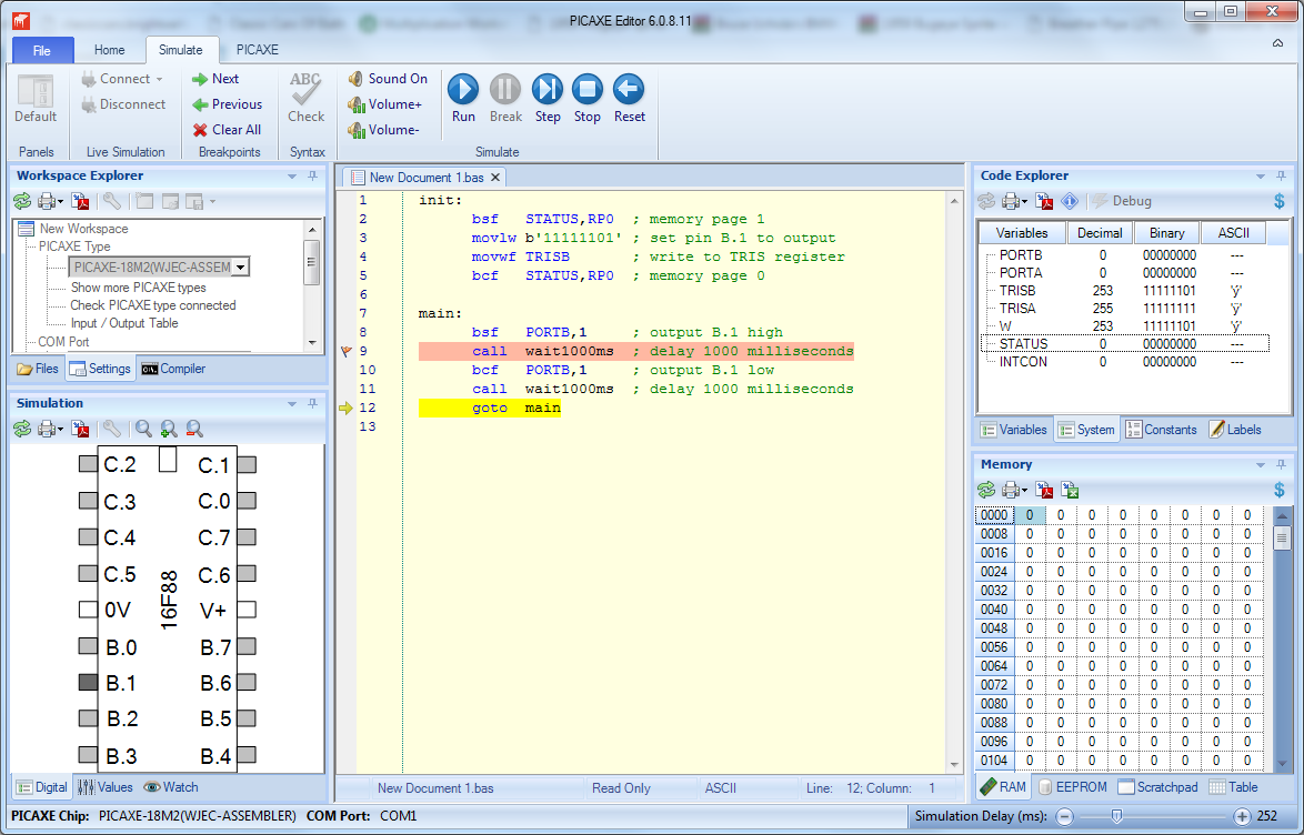
Assembler programs can also be simulated line-by-line on screen before download to the real chip.
Note that the PICAXE-18M2 chip is emulating a 16F88/assembler and so the chip does not operate at quite the same speed as a PIC programmed in raw assembler code. However the PICAXE system is still a very convenient, easy to use and low cost method to teach the WJEC requirements via on-screen simulation and real-life downloads.
Recommended PICAXE hardware
The recommended hardware is either an AXE056 T4 Trainer board or an AXE091 experimenter board, both fitted with a PICAXE-18M2 microcontroller.
The tutorials on this website assume the following input/output devices, as used on both these project boards.
B.0 LED via 330 resistor to 0V
B.1 LED via 330 resistor to 0V
B.2 LED via 330 resistor to 0V
A.0 miniature LDR * (10k pull-down resistor)
A.1 10k pot between power rails
A.2 DS18B20 temperature sensor (4k7 pull-up resistor)
A.7 push switch (10k pull-down resistor)
* Note that due to RoHS regulations LDRs are no longer fitted by default to Revolution pre-assembled products. However as RoHS regulations only apply to the sale of ‘finished goods’ an LDR may still be purchased as a separate component and soldered to the project board after purchase.
Migrating from AQA or OCR Electronics A level
Schools migrating from teaching AQA or OCR A level syllabi using PICAXE should find it relatively simple to switch to the new WJEC A level syllabus.
The main differences to AQA/OCR A level are:
- Focus is on 18 pin PICmicro pinout devices (not 28 pin PICMicro/AVR)
- The assembler mnemonics used are the ‘real’ Microchip MPASM mnemonics
- The interrupt taught is a rising or falling edge signal on one input pin
- Timers and tables are no longer part of the exam syllabus
Getting Started
Please refer to our to our two free tutorial sections:
- Getting Started with WJEC - Microchip Assembler
- More tutorials for WJEC - Microchip Assembler
AXE056 T4 PICAXE-18M2 Trainer

A PICAXE-18M2 tutorial board with various input/output devices connected to both PORTA and PORTB. Ideal for demonstrating all the assembler code examples. Starter pack includes power supply and AXE027 cable. Details
PDF ↓ Buy Now-
AXE091U AXE091 Experimenter

This board supports all PICAXE chip sizes and also has a breadboarding area for designing your own circuits. Starter pack includes 18M2 chip and AXE027 cable. Details
PDF ↓ Buy Now -
AXE015M2 PICAXE-18M2 Microcontroller

Spare PICAXE-18M2 microcontroller, as supplied with AXE056 and AXE091. Details
PDF ↓ Buy Now -
AXE027 AXE027 USB Cable

Spare PICAXE download cable, as supplied with AXE091 and AXE056. Details
PDF ↓ Buy Now -
AXE029 AXE029 Adapter

Small adaptor PCB to enable AXE027 to be used with a breadboard. Details
PDF ↓ Buy Now