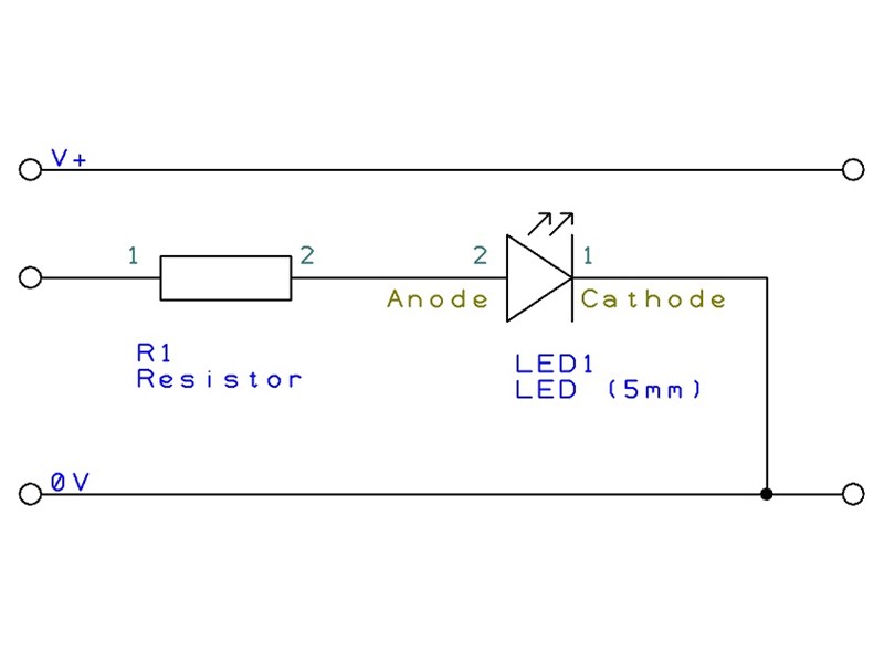
A Light Emitting Diode (LED) can be connected directly to a PICAXE output pin (using a current limiting resistor in series). It is more common to connect the LED/resistor betwwen the output pin and 0V, however it may also be connected between the output pin and V+.
LEDs are polarised, and so only work one way around. Generally the long leg is the anode (positive) leg, and there is also a flat edge on the plastic casing marking the cathode (negative) leg.
LED
Schematic
PCB
Flash an LED
Flash an LED connected to output pin B.1 on and off every 5 seconds
- Code Example:
-
main: high B.1 ; Switch on output B.1 pause 5000 ; Wait 5 seconds low B.1 ; Switch off output B.1 pause 5000 ; Wait 5 seconds goto main ; Loop back to start
Copy Code Submit an Example
Create Module
The LED create module.
The LED will light with a 'high' command and switch off with a 'low' command.
Bill of Materials
Description | Code | Qty | |
---|---|---|---|
Red 5mm LED | LED001 | 1 | Buy Now |
Green 5mm LED | LED002 | 1 | Buy Now |
Yellow 5mm LED | LED003 | 1 | Buy Now |
Blue 5mm LED | LED004 | 1 | Buy Now |
Pink 5mm LED | LED014 | 1 | Buy Now |
330 ohm resistor (pack 100) | RES330R | 1 | Buy Now |
Simulation
Submit Your Own Code!
You must be logged in to submit code examples. Login now.
Share