An RGB LED contains three separate LEDs coloured red, green and blue. These are the primary additive colours of the light spectrum. By lighting one or more of the LEDs and at different brightnesses nearly any colour of the visible spectrum can be obtained.
Each individual LED can be switched on or off which allows for six colours plus off or a specific brightnesses for a LED can be set by using a PWM signal.
This program cycles an RGB LED between its red, green and blue colours. The RGB LED red, green and blue anodes should be connected with inline resistors to output pins B.1, B.2 and B.3 respectively. The LED's common-cathode should be connected to 0V..
Code Example:
main:	high B.1	; Turn the red LED
	pause 500	; Keep the red LED on for a while
	low B.1		; Turn the red LED off

	high B.2	; Turn the green LED on
	pause 500	; Keep the green LED on for a while
	low B.2		; Turn the green LED off

	high B.3	; Turn the blue LED on
	pause 500	; Keep the blue LED on for a while
	low B.3		; Turn the blue LED off

	goto main	; Repeat
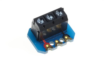
An RGB LED may be connected to three generic terminal block create modules.
The R, G and B legs of the LED should go to the centre connectors of each terminal block (each through a 330R series resistor). The common cathode leg should connect to one of the 0V connections of the terminal blocks.

Share