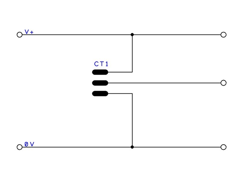
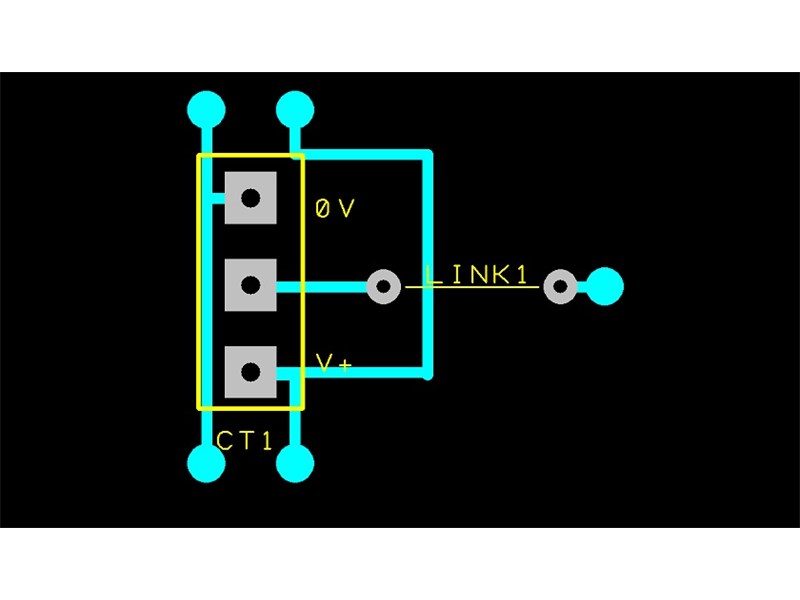
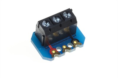
A screw terminal block is a convenient means to connect arbitrary signals and make temporary connections to a PICAXE circuit. Wires from an input switch (sensor or other circuit) are inserted into the terminal block and the associated screw clamps the wire into place. Each connection to the terminal block is insulated from the others.
The following program will use a LED on output pin B.1 to indicate the state of a digital input signal to input pin C.0. When the input signal is high the LED will light, when it is low the LED will be turned off.
Use a 1k resistor to connect the centre contact of the terminal block to one end contact or the other. When the centre contact is not connected to the end contacts the input will be 'floating' and the LED may be on, off or flickering.
Code Example:
main:	if pinC.0 = 1 then	; When input signal is high (1) then
	  high B.1		;   Turn LED on
	else			; Otherwise, it is low (0) and
	  low B.1		;   Turn LED off
	end if
	goto main

Share