Free PCB software
There are now a number of very good, completely free, PCB software options available to schools. As an example DesignSpark PCB is a full feature, completely free of charge, option that can be used on school networks and by students at home. It is ideal for PICAXE projects.
However if you have never used PCB software before, as is normally the case with school students trying to make their first electronics project, the PCB creation process can often be daunting and difficult, particularly within the very limited timescales of school project work. Therefore we have developed special PICAXE component libraries, and Create PCB 'modules' to make this development process much simpler.
Naturally you could always purchase and use one of our project boards, but we also like to actively encourage students to make their own PCBs. So the Create modular sections of PCB have been designed to help you easily take the first step on the PCB creation ladder. By simply cutting and pasting the provided ‘modules’ onto a design, and then joining the sections together ‘dot to dot’ style, you can often design a full PICAXE project PCB in less than 10 minutes!
All modules use a single sided PCB, wide tracks and large solder pads for ease of manufacture.
Design Process
The design process is very straight forward, simply first select the ‘building blocks’ of your circuit from the Circuit Creator pages of this website, for example:
- PICAXE motherboard (in this example we are using the 08M2)
- Power supply type (4.5V battery box)
- Output Components (two LEDs and a piezo sounder)
- Input Components (switch and LDR)
All these examples have been created with the free DesignSpark PCB software.
Step by Step Guide
To use this system you must download and install the PICAXE Create library for DesignSpark PCB. Full instructions on how to do this are here.
Step 1
Each of these modules is provided as a separate file, so the first task is to simply open the PCB module files and cut and paste the sections onto the same PCB design. Note whole modules can be rotated 90 degrees if required (as shown by the piezo module, which has been rotated to fit on the bottom of the PCB).
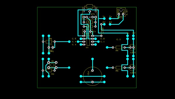
Normally you would then reduce the size of the PCB by moving the components closer together where possible, however for clarity in these pictures we have left all components in their original positions.
Step 2
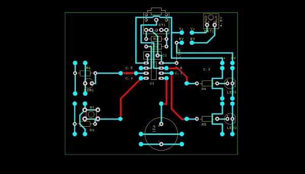
Now we need to use the track tool to connect each of the 5 i/o modules to the correct PICAXE-08M2 pin.
The tracks are shown in red here to illustrate where the added tracks are but they will be given the normal track colour when you actually add them.
Step 3
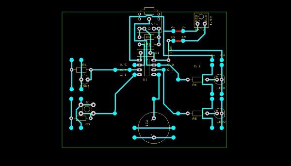
The next task is to draw two tracks to connect the selected power supply module to the motherboard (see top right of the picture).
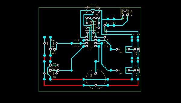
Step 4
The last task is to then connect the two parallel power rails (V+ and 0V) all the way around the board. Make sure all the modules are connected together (note the four short tracks added on the right hand side to link the supply to LED1 and then from LED1 to LED2). Your design is then complete!
Outputting the design
Your design can now be:
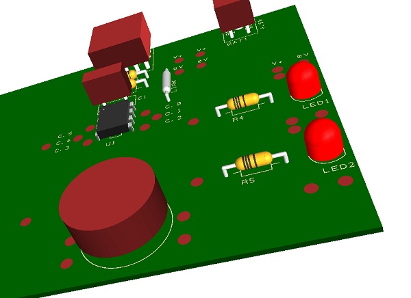
- displayed as a '3D image' to act as a reference during assembly
- exported as PDF or bitmap image for the student's portfolio
- printed for photo-etching masks
- used to export a Bill of Materials
- converted to Gerber files for commercial production. You could even use isolation routing software such as CopperCAM to manufacture the PCB on a milling machine.